
A controller failure does not have to mean a complete interruption to an industrial process. With the right architecture, automation engineers can prepare a system to respond to specific hardware and communication faults while keeping essential functions available.
B&R Industrial Automation offers redundancy options for its X20 platform that address several potential weak points: the controller itself, the communication network, and the power supply to supported components.
The important engineering decision is knowing which failures need to be covered—and how the different layers of protection should work together.
Two Controllers, One Control Strategy
In a redundant B&R control system, two compatible X20 controllers operate as a pair. One runs as the active controller, while the second remains ready to take over if the active unit fails.
A dedicated interface, the X20IF10X0 redundancy link module, synchronises application data between the controllers. B&R's Redundancy for control systems – Possibilities and examples manual describes synchronisation in the microsecond range and a switchover time of no more than two cycles under the documented conditions.
The design is integrated into B&R's real-time operating system, so redundancy can be configured within the engineering environment rather than built entirely as a separate application.
The manual identifies the following benefits:
Automatic switchover following supported controller failures
Microsecond-range application data synchronisation
A maximum switchover time of two cycles
Support for controller replacement without machine downtime under the specified conditions
Support for bumpless software updates
The X20CP3684 is one of the controller models listed as supporting this functionality. The final selection must account for the full compatibility requirements, including software, interface modules, licensing, and application constraints.
Protecting the Communication Path
A backup controller addresses one failure point, but it cannot protect a system from every network fault. If a communication cable or network device fails, connected equipment may still lose access to the control system.
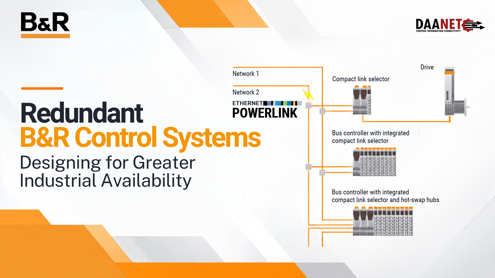
B&R provides two principal POWERLINK network redundancy approaches: cable redundancy and ring redundancy.
Cable redundancy: Two separate network lines
Cable redundancy uses two physically separate communication lines. Supported devices connect to both through suitable link-selection hardware.
If a fault interrupts one line, the functioning line can continue carrying communication. The approach is particularly relevant when separate cable routes are desirable or required.
Depending on the design, B&R components such as the X20IF2181-2 interface module, X20HB8884 compact link selector, and X20BC8084 bus controller can be used.
The two networks must have matching logical topologies, including hub arrangements, cable lengths, and telegram-transfer direction. A simultaneous fault affecting both networks can still cause devices to become unavailable.
Ring redundancy: An alternative route through the network
A POWERLINK ring connects supported devices in a loop, with the final connection returning to the ring manager.
During normal operation, the manager monitors the ring. When an interruption is detected, it can direct communication around the remaining available path so that other connected nodes continue receiving data.
Ring redundancy can provide a relatively simple way to improve network availability. B&R also documents partial-ring arrangements and specific applications involving slip rings.
There are limits, however. All devices must be suitable for the chosen topology, and two separate interruptions can isolate the nodes between them. Network planning must account for these conditions before the system is commissioned.
When Controller and Network Protection Work Together
For applications with stricter availability requirements, controller redundancy can be combined with supported POWERLINK network configurations.
This creates a broader protection strategy: the redundant controller pair addresses certain controller failures, while the network arrangement addresses specific communication faults.
B&R's documentation illustrates combinations involving a basic POWERLINK network, ring redundancy, and cable redundancy. Each arrangement has its own configuration requirements and supported failure scenarios.
The objective is not simply to install more hardware. It is to identify what could interrupt the process and choose an architecture that responds appropriately.
Do Not Overlook the Power Supply
Power is another potential point of failure. B&R's X20 system supports redundant supply arrangements for specified controller components, including the X2X Link supply and supported standalone devices or bus controllers.
One important limitation is that redundant X20 supply modules do not themselves provide redundant power to I/O modules and their connected sensors and actuators. Those loads require a separately designed power supply arrangement.
For this reason, a system review should consider the controller, communications, and power distribution together rather than treating controller redundancy as complete protection for the installation.
Five Questions to Ask Before Designing a Redundant System
1. What must remain available? Identify the critical control functions and the consequences of losing them.
2. Which faults must the system withstand? A controller failure, a broken network cable, and a power supply failure are different events requiring different measures.
3. Are the components compatible? Confirm controller models, interface modules, hardware revisions, software versions, and licensing against current B&R documentation.
4. Is the network topology appropriate? Cable and ring redundancy have different wiring rules, constraints, and failure behaviour.
5. Has the design been tested? Validate switchover, communication recovery, and the behaviour of connected devices under the expected operating conditions.
A redundant architecture can reduce the consequences of defined failures, but it does not guarantee uninterrupted operation under every possible fault. Configuration, validation, and maintenance remain essential.
Planning Your Next Automation Project?
A well-designed control system begins with a clear understanding of the application and its availability requirements. B&R's X20 redundancy options give engineers several ways to address potential failures, from controller-level protection to alternative network paths and supported power supply arrangements.
DAANET helps Australian businesses explore industrial automation components and solutions suited to their engineering requirements.
Talk to DAANET about your control system requirements.
Website: https://www.daanet.com.au
Sales: sales@daanet.com.au
Technical support: techsupport@daanet.com.au
Phone: 1300 322 638
Technical reference
B&R Industrial Automation, Redundancy for control systems – Possibilities and examples, Version 1.31, July 2025.
Consult the relevant B&R manuals for current compatibility, configuration, licensing, and hardware revision requirements.
